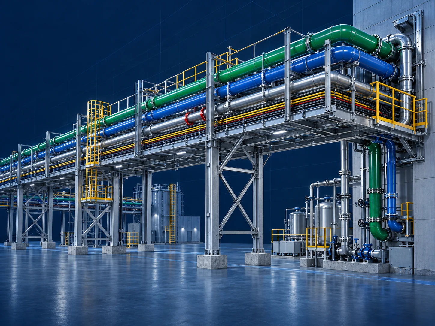
Fix the coordinate system
Base geodesy, control points, elevation system and export rules must be agreed upon before the first merged model. It's cheaper than having to fix the biased models of all disciplines later.
Infrastructure BIM
System BIM coordination for bridges, roads, tunnels, railways, stations, airports, ports and other transport and civil infrastructure facilities.
For infrastructure, it is not enough to simply combine models. Long linear geometry, a single coordinate system, structures, existing and new networks, process systems, temporary works, construction phasing and data that are subsequently transferred to the operations team need to be agreed upon.
Discuss the infrastructure projectFeatures of the infrastructure
The main difference of the infrastructure project is the scale and number of interfaces. One corridor can simultaneously include a road or track, bridges, tunnels, underground networks, drainage, stations, technical structures and areas designed by different teams.
The biggest problems arise not only because of geometric collisions. Different coordinate systems, incorrect elevations, outdated data on existing networks, incompatible boundaries of contract packages, route changes, unaccounted for temporary structures and lack of uniform model exchange rules become critical.
Key rules need to be fixed before active coordination: coordinate system, division of the object into zones and plots, limits of responsibility, format of models, update rules, status of output data and list of information for construction and operation.
BIM coordination of infrastructure is the control of space, geographic reference, engineering solutions and information throughout the project.
Critical nodes
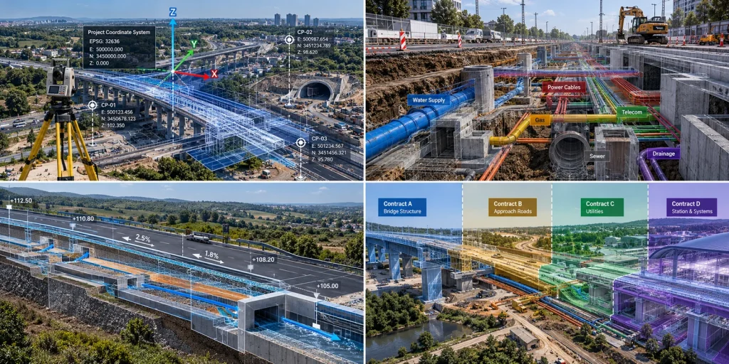
In large infrastructure projects, models from different disciplines and contractors must work in one geodetic system. Even a small error in a base point, a turn or an elevation mark can create dozens of pseudo-collisions or, on the contrary, hide a real conflict.
Before starting coordination, it is necessary to fix the coordinate system, control points, height system and rules for transferring models between teams.
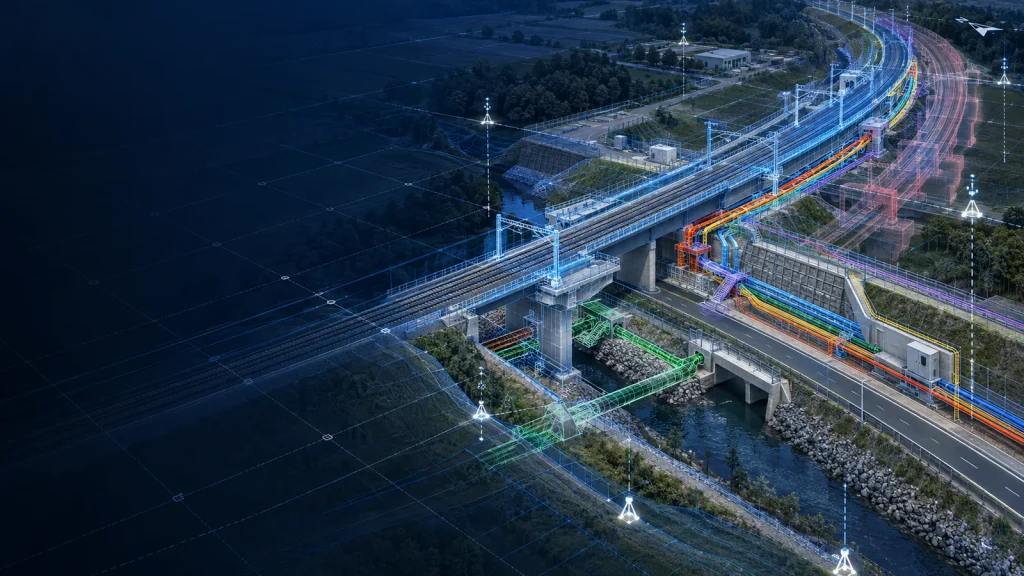
On roads, railways, stations and urban infrastructure projects, the actual position of existing networks often differs from the old documentation. Cables, water, sewer, gas, communication and drainage may have incomplete or inaccurate coordinates.
In a BIM environment, it is important not only to show the network, but also to understand the source and reliability of its data. Critical intersections need to be confirmed by survey, geodesy or additional field data before issuing construction decisions.
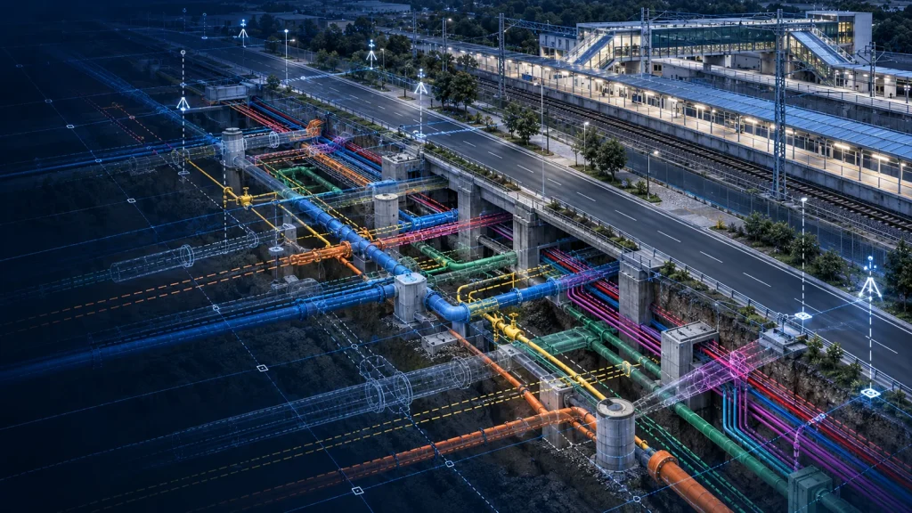
For roads, tunnels, platforms, drainage and gravity networks, it is not enough for the element to simply pass between other systems. It must maintain the required slope, marks and connection points along its entire length.
Locally, the pipe may not have collisions, but after bypassing the structure, lose the slope or form a low point. Such problems are detected only when checking the complete route, and not a separate fragment.
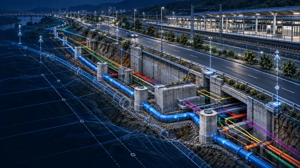
A bridge can be designed by one team, approaches by another, external networks by a third, and station systems by a fourth. Each individual model may be correct, but there are inconsistencies in markings, holes, traces and connection points at the border of the packages.
Such interfaces should be allocated as separate coordination areas with a designated person in charge, a deadline for closing the issue, and controlled re-checking after changes.
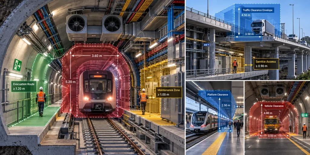
In tunnels, on railways, bridges and stations, it is necessary to keep the dimensions of rolling stock, vehicles, passages, evacuation routes and service access.
BIM coordination must check not only the solid geometry of the elements, but also the areas that must remain free during operation and maintenance.
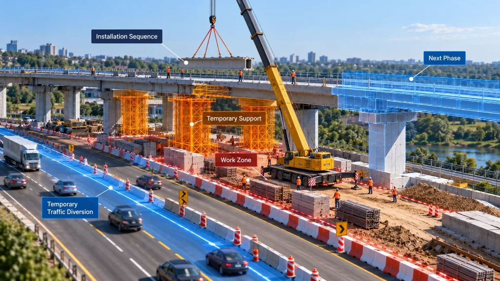
Cranes, temporary supports, installation sites, detours, traffic closures, temporary drainage and relocated networks are often missing from the final model, but they determine the feasibility of the work.
For complex areas, it is useful to check the model together with the calendar sequence: where the equipment will be located, when the area is vacated, which route remains available and whether parallel operations are blocking each other.
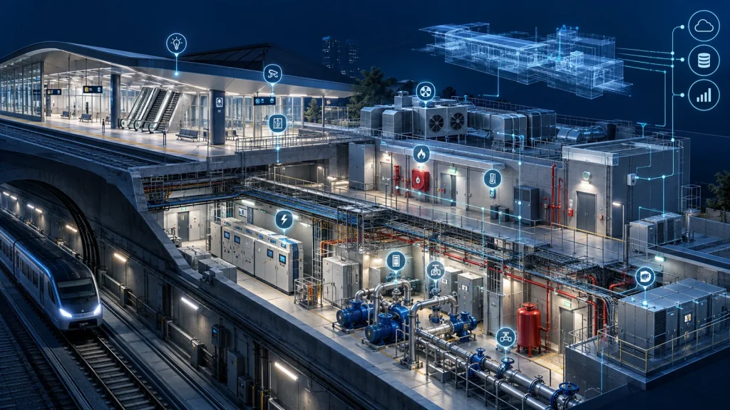
A station, tunnel or transport hub contains thousands of components: shields, fans, pumps, valves, sensors, cables, lights, doors, fire equipment and other assets.
If the rules for naming, classifying and filling attributes are not defined at the beginning, at the end of the project you have to manually restore the connection between models, drawings, passports and actual equipment.
01 / Bridges and structures
In bridges and overpasses, the main coordination task is to relate the track geometry to the actual structure and elements that are manufactured or assembled with high precision.
It is important not to lose the geometric connection between the calculation model, the structural BIM model, the working documentation and the data transmitted to the manufacturer. An error at this transition may appear already during steel fabrication or installation.
02 / Roads and corridors
For roads and transport corridors, coordination begins with the correct axis, longitudinal profile and digital terrain model.
All disciplines must work with one relevant geodetic framework. Otherwise, the models may look coordinated locally, but not match when brought to life.
03 / Tunnels
The tunnel is a long technical corridor with a strictly limited transverse profile. Structures, track or carriageway, ventilation, fire protection, drainage, electricity, communication, automation and evacuation infrastructure must be coordinated on a kilometer length.
In Gilon Railway Tunnels Ziggurat operated with two parallel railway tunnels of approximately 4.6–4.7 km and 18 emergency crossings. Here you need to control the continuity of routes, repeated nodes, access and interaction of systems along the entire facility.
04 / Railways and stations
In railway projects, track geometry is the basis against which platforms, structures, engineering systems and equipment are coordinated.
Ziggurat's portfolio includes the Dayan Center Railway Station and the West Yavne Railway Station for Israel Railways, as well as the NETA Urban Transportation Control Center in Tel Aviv. This experience combines transportation geometry, building structures and engineering systems in one environment.
05 / Terminals
An airport or a large transport terminal combines a building, a technological complex and a continuous operational activity. Baggage or cargo equipment, access systems, telecommunications, vertical transport, specialized service areas and external transport infrastructure are added to standard engineering systems.
BIM management is especially important here: several work packages can simultaneously change one area, so the team must know exactly which model is relevant and which changes have been agreed upon.
Interdisciplinary model
In Infrastructure BIM, it is important to ensure not only the absence of collisions, but also spatial continuity, accurate georeferencing, control of interfaces, real construction sequence and data manageability along the entire length of the object.
BIM Management
In a large-scale infrastructure, the main risk is often not the lack of information, but the fact that different teams are working with different versions of it.
For large stations and transport nodes, the number of assets can be measured in the tens of thousands. If data on equipment, installation location, documentation and status are not structured during design and construction, handing over to the operator becomes a separate major information cleanup project.
Model and change managementPractical principles
Base geodesy, control points, elevation system and export rules must be agreed upon before the first merged model. It's cheaper than having to fix the biased models of all disciplines later.
Junctions "tunnel-station", "bridge-road", "track-platform", "building-external networks" and contract boundaries should have their own checks and responsible.
An existing network from an old drawing cannot be perceived in the same way as a network confirmed by geodesy. The model should be clear about which data can be trusted.
For bridges, stations, tunnels and reconstruction of existing infrastructure, temporary structures, machinery, detours, phased switches and access to the work area must be considered.
Asset IDs, classification, system names, and required attributes are best defined prior to mass populating models. Then the operator will receive structured information, and not a set of incompatible files.
Ziggurat's portfolio includes Gilon Railway Tunnels, Dayan Center Railway Station, West Yavne Railway Station and NETA Urban Transportation Control Center. These types of facilities include long engineering routes, complex transportation nodes, limited technical spaces, and coordination of many systems.
Ziggurat services
Interdisciplinary coordination of geometry, structures, engineering and transport systems with conflict analysis, feasibility testing and development of technically agreed solutions.
View the serviceControl of models, versions, coordinates, asset data, common data environment and information processes between the participants of the infrastructure project.
View the serviceDirections of Infrastructure BIM
Coordination of the route, terrain, drainage, existing networks, artificial structures and phased construction.
Coordination of span structures, supports, joints, drainage, embedded parts and data for manufacturing and installation.
Coordination of track, platforms, structures, engineering systems, signaling, communication and station infrastructure.
Coordination of tunnel geometry, ventilation, drainage, fire, electrical, communication and evacuation systems.
Coordination of engineering and technological systems, passenger or cargo areas, external infrastructure and phased reconstruction.
Military and defense objects are presented in a separate branch - "Military and defense objects" .
Your infrastructure project
If you are working on a bridge, road, tunnel, railway, station, airport, port or other transport infrastructure object, send us the existing project materials.
We will assess geometry, structures, engineering systems, package boundaries, output quality and information requirements and determine the required scope of BIM coordination and BIM model management.
Discuss the infrastructure projectFAQ
In the infrastructure, it is necessary to control long distances, georeferencing, gradients, existing networks, traffic dimensions, contract boundaries and phasing of construction. A locally correct model may be incorrectly integrated into the overall corridor.
A single coordinate system, geodetic basis, division of the project into zones responsible for interfaces, rules for exchanging models, status of initial data and requirements for final information.
The model allows you to combine new solutions with the actual state, check temporary schemes, phased switching, equipment access and interaction with networks and structures that remain in operation.
It is necessary to check the continuity of systems on a long length, traffic dimensions, drainage, ventilation, fire protection, emergency transitions and service access.
Due to the large number of models, contracts and changes. Without version control, coordinates, and statuses, even a well-modeled system can be coordinated with out-of-date data.
For large objects, this is often appropriate: BIM provides detailed geometry and technical information, while GIS helps to work with spatial context, parcels, networks and geographically distributed assets.
When the baseline, structural and engineering solutions are sufficiently established for verification, but key joints, networks, openings, equipment and building packages can still be changed without expensive impact on fabrication and installation.